- Estimate the torque necessary to raise a load of 100kN. [ 501 Nm]
- If the screw rotates at 1 Hz ascertain the power input to the screw, and the combined efficiency of screw and thrust bearing. [ 3.15 kW 19%]
- If bearing friction is eliminated by a rolling thrust element, show that the screw is self-locking and determine the torque necessary to lower the load. [ 106 Nm]
- The thread is further lubricated to halve the friction coefficient. Does this result in overhauling behaviour? What is the effect of lubrication on performance here?
 The two arrangements are identical except for the spring washer's position. The washer is the only element of the assembly having appreciable compliance - the bolt and joint components are essentially rigid. The bolt is initially tightened to Fi , then the external load P is applied.
If Fw is the washer load, Fb is the bolt load, and Fj is the load transferred between the joint components 1 and 2 prior to separation, plot for each arrangement Fb and Fj versus the external load, P. Identify the separation load P*. Hint : note that prior to separation Fw must be constant at Fi , so equilibrium alone gives the information required.
Evaluate the bolt load when P is 2 kN and Fi is 10 kN. [ 12 kN and 10 kN]
 cover of a pressurised cylinder is secured by ten bolts whose aggregate stiffness is a quarter of the total joint stiffness. Each bolt is tightened initially to 5 kN, then a constant external load of 20 kN is applied to the cover by the pressurised contents of the cylinder.
Plot the variation of bolt and joint loads against external load, and evaluate the maximum load on each bolt, the minimum total joint load, and the separation load. [ 5.4, 34, 62.5 kN]
 The steel bracket is bolted to steel ceiling joists by two bolts of class 8.8 and 48 mm grip length. What tightening torque should be used, and what is the corresponding load in each bolt when the 40 kN external load is subsequently applied? [ 480 Nm; 125 kN]
 by a self-energising seal and a number of identical bolts. The fluid pressure is essentially constant at 6 MPa. Select suitable class 8.8 bolts for this duty given that the ratio of bolt spacing ( around the ¿180 mm pitch circle ) to bolt size should not exceed 10 to minimise flange bending, and should not be less than 5 in order to allow spanner access. A safety factor of three is applicable to the external load on the assembly.
If the strength of the motor
 bolt and which is elastically compressed may be assumed to be a cylinder of annular area 300 mm2.
Determine the safety factor appropriate to the reversing load, with
- zero initial bolt load, [ 2.0]
- initial bolt load just sufficient to prevent separation, [ 6.8]
- bolts tightened initially to 70% proof. [ 3.6]
 A connecting link consists of two circular sections of forged aluminium alloy ( E = 71 GPa ) spigotted and joined by six equally spaced steel studs, M8x1.25 class 10.9, having shanks of reduced diameter with transition radii of 20 mm and polished surfaces.
- Explain briefly but clearly why the studs are provided with reduced shank sections.
- To what minimum diameter can the shanks be reduced without compromising the fatigue strength of standard studs with unreduced shanks? [ 5 mm]
- Studs with 6 mm diameter shanks are used, tightened to half their yield strength ( caution : occurring where? ). What is the factor of safety when an alternating axial load of 60 kN amplitude is applied? ( caution : evaluation of the bolt load needs care ) [ 0.92]
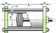
 The components of an hydraulic actuator are of steel - the cylinder is of bore D = 100 mm, wall thickness t = 10 and length L = 300 mm. The thickness of the end brackets is w = 20 mm, and they are connected together by five M12x 1.75 grade 5.8 bolts, tightened to 75% proof. In operation the cylinder is pressurised between 0 and 4 MPa.
- Determine the stiffnesses of the bolts and of the joint assuming that the cylinder is compressed uniformly and that the end brackets are rigid. [ 344, 2240 kN/mm]
- Find the mean and alternating stresses in the bolts. [ 289, 4.7 MPa]
- Estimate the endurance limit of the bolts based upon 50% reliability. [ 115 MPa]
- What factors of safety guard against fatigue failure and against static failure? [ 8.3, 9.8]
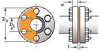
 A pipe joint incorporates flanges of width w = 12 mm together with a full face gasket of bore Di = 150, outside diameter Do = 250 and thickness t = 2 mm. The gasket material has a stiffness of 100 MPa/mm with m= 1.5 and y= 2 MPa.
Neglecting rotation, assess the joint's suitability to withstand fluid pressure fluctuating between 0 and 1 MPa, if six M10x1.5 class 5.8 steel bolts are used.
| As = β n C P / Se where | ||
| n is the safety factor corresponding to the external load P, | ||
| As is the bolting stress area required to support P, and | ||
| β = 1/2 ( 1 + Se /Su ) / ( 1 - σi /Su ) and lies generally in the range 1.3 ≤ β ≤ 2.1 for rolled threads, steel classes 5.8 through 12.9, and an initial load of between 75 and 90% proof. | ||