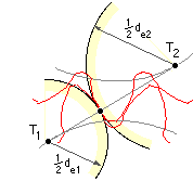
 Flank pitting is caused by alternating normal pressure on the contact surfaces of the teeth. It is found to occur most frequently at the pitch circle - where relative sliding of the teeth is zero and the hydrodynamic lubricant film tends to break down - so attention is focused on this location. From previous work on Hertzian contact stresses, the maximum normal pressure, p, between contacting cylinders of equivalent diameters de1 and de2 and length L, and on which the normal force is F, is :-
( 20 ) p2 = ( 2 E* F / π L ) ( 1/de1 +1/de2 )
where 1/E* = ( 1 - ν12 ) / E1 + ( 1 - ν22 ) / E2
ie. E* = E / 2 ( 1 - ν2 ) if the materials are identical, and
= 113 GPa if the materials are both steel.
This simplified model is adapted to involute teeth contacting at the pitch point as follows :-
Making these adjustments to ( 20), invoking ( 12) ( 15) ( 16) and introducing a constant of proportionality - to correlate simple model with actual tooth - leads to the final design equation for pitting resistance :
( 21 ) ( π2 m3 β N1 z12 I / Ka Kv Km KR2 E* P ) . ( Sc CL ) i2 ≥ 1 ; i = 1,2

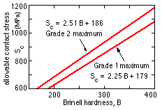
in which Sc is the allowable contact stress for the gear tooth material. Values are cited in AGMA 2001 - maximum values for two grades of through-hardened materials are shown here :
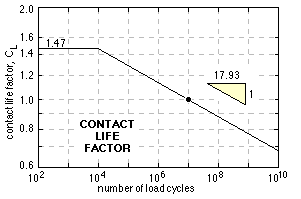
CL is a gear's contact life factor - the normalised load-life curve under repeated contact loading as explained above. The AGMA relationship for through-hardened steels is given here.
 The implications of the slope of the (log -log) load-life plot must be appreciated - a load increase of only 2% leads to a life reduction of 30%.
The contact design equation ( 21) is applied to the two gears individually in the same manner as is the bending design equation ( 19) - again, the first bracketed term is common to both gears. In applying ( 21) to design therefore, the gearset will be limited by the weaker gear - that which has the lesser Sc CL product.
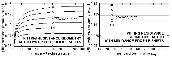
The remaining parameter in ( 21) as yet unexplained is the pitting resistance geometry factor, I, which correlates the stresses between the simple Hertzian model and actuality. It is analogous to J, and like J its value depends upon tooth numbers and profile shifts, and is obtainable from AGMA 2001 or calculated by the Macintosh program "Steel Spur Gears".
The value is the same for both gears and tends to sin2α / 4(1+z1 /z2 ) as the number of pinion teeth z1 becomes large. It is plotted below corresponding to the profile shifts of both gears being either zero or in the middle of the practical range (Fig G). When profile shifts are mid -range the I-factor is essentially dependent only upon the gear ratio ρ, and may be approximated by :
( 22 ) I ≈ ( 0.0404 + 0.1127 ρ ) / ( 1 + 0.70 ρ ) in which ρ = z2 /z1 ≥ 1

|
Having developed a theory for each of the two gear failure mechanisms, it is now possible to apply them.