EXAMPLE
Complete the last example and find the failure load, given the previous results σE = 401, σP = 840 MPa.
Inserting these two values into the interaction models and solving for the failure load gives :-
CEGB R6 model - from ( 3) σF = 382 MPa
'circular' model - from ( 4) σF = 362 MPa - conservative as noted.
EXAMPLE
Using the same 20x2 mm long strip, apply the R6 approach to find the critical crack length for a 250 MPa load.
This is the reverse problem to the above - a closed form solution is impossible, so a graphical or trial- and- error approach must be adopted - thus :-
| Trial normalised crack size α | 0.1 | 0.2 | 0.3 | 0.4 | 0.5 | 0.6 | 0.63 | 0.7 |
| σE = KIc /( Y√(παw)) corresponding to α | 887 | 615 | 486 | 401 | 335 | 279 | 263 | 227 |
| σP = Sy ( 1 -α ) corresponding to α | 1260 | 1120 | 980 | 840 | 700 | 560 | 518 | 420 |
| σF from ( 3) corresponding to σE and σP | 800 | 578 | 462 | 382 | 320 | 265 | 250 | 214 |
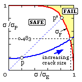
 The stress ratios computed from the table are plotted to illustrate the fatigue locus as crack size increases.
Repeating this for comparison purposes using the more conservative 'circular' model.
Despite this model's equation being simpler than the R6 equation, a closed form solution is impossible and the above table must be repeated using ( 4) rather than ( 3).
Thus at α = 0.6 from the above table using ( 4) σF = 1/√( 1/2792 + 1/5602 ) = 250 MPa
The critical crack size predicted by the 'circular' interaction model is therefore 0.60x20 = 12 mm - not significantly different from the R6 conclusion.