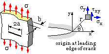

A crack of length 2a extends right through an infinite elastic flat plate of small thickness b. The plate is loaded by a background stress, σ, normal to the crack. From equilibrium, compatibility and the linear elastic constitutive law, the stresses in an element located at ( r, θ ) close to the crack tip, may be shown to be :-

|
| - | The stress field ( 1) arises from the crack itself and not directly from the background stress. If the element were well removed from the crack tip vicinity then the background stress would dominate, ie. σy --> σ ; σx , τxy --> 0.
|
| - | The stress components ( 1) are of the general form :-
stress component = constant ( K ) x function of element location ( r, θ ) The constant is termed the stress intensity factor and embodies the geometry and loading. Ko refers to the particular centrally cracked infinite plate arrangement considered above. K is an amplitude, a scale factor, a measure of the intensity of the singularity and the severity of the stress field immediately adjacent to the crack tip - and it is the near-tip field which directly influences crack advance If the stress intensity factor were to double, due to doubling of the load for example, then all stress components on all elements would also double. Note the inherent linearity here. |
| - | A compressive background stress tends to close the crack and is therefore not deleterious ( as long as it is steady ).
|
| - |  Provided the loading is tensile, mode I, then for geometries other than the infinite plate with central through -crack, and background loads other than a uniform tensile stress, the stress field close to the crack tip is identical in form to ( 1) - since the near-tip region is not directly affected by distant events. However the field strength, that is
 the stress intensity, KI corresponding to mode I, will reflect the particular geometry and loading, and will thus differ from Ko.
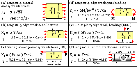
A configuration factor Y = KI /Ko reflects this difference. Values of Y for various configurations appear in the literature. Defining the normalised crack size as α = a/w, approximations for some common cases and for α ≤ 0.7 are shown here. |
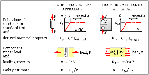
| - | The above analysis would be completely useless if the aim were to calculate the maximum equivalent stress ( in order to correlate with the yield to find the safety factor for example ) because all stress components theoretically tend to infinity as r --> 0. Stress redistribution prevents this happening in practice of course, but this is a plastic phenomenon, irrelevant to elastic analyses. So, rather than using stress magnitude as a measure of loading severity ( and hence a basis from which to reckon safety ) we use stress intensity instead. The stress intensity factor is one of a number of measures whose values describe the damage due to the crack - other common parameters are the 'crack opening displacement' ( COD, see below ), and the 'J-integral' ( an energy integral around a path enclosing the crack ).
The material's fracture toughness ( Kc ) can be recognised as just the critical maximum stress intensity ( K ) which the material can withstand without catastrophic crack propagation. An additional subscript 'I' refers to the most common tensile mode I loading. The distinction between stress intensity, KI, a crack characterising parameter and fracture toughness, KIc, a material parameter should be clearly understood. |
 in fracture mechanics is similar in principle to the determination of safety factor in traditional Strength of Materials contexts - a parameter expressing loading severity is compared to the maximum severity which the material can withstand ie. a material property. The two appraisal approaches are compared here, though it must be pointed out that in Fracture Mechanics it is more usual to cite the fatigue life which remains, rather than a factor of safety per se. Life aspects are considered below.
There are two common forms of fracture toughness test specimen, the 'single edge notch' ( SEN, case ( e) above ) and the 'compact tensile specimen' ( CTS, case ( c) ). In both of these a crack is started by machining a chevron notch in a specimen of standard proportions ( thickness b = w/2 ), then fatiguing the specimen to obtain a sharp crack front. The load - bending or tension respectively - is then applied and increased until catastrophe occurs. In principle, the maximum load in conjunction with the configuration factor ( Y) corresponding to the final crack size enables the fracture toughness to be calculated. Testing in practice is not quite so straightforward as this might indicate, eg. we shall see that size effects also have to be reckoned with.
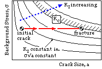
 It is now possible to appreciate how fatigue occurs.