We refer to tension, shear, bending and torsion as elementary load building blocks because the loading which is applied to most components is a combination (superposition) of these four - for example, a rotating shaft which transmits power is subjected not only to torsion, but usually also to bending and to direct shear. The similarities and differences between the load building blocks are illustrated here.
This first example applies the building blocks to the analysis of a bent cantilever.
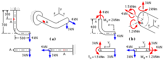
The bent cantilever, shown at ( a) below, is made from 60 mm diameter rod. Determine the stress components at the surface element A lying in the horizontal plane of the cantilever's centreline.

|
| Tension P = 4 kN | |
| σ = P / A = 4E3 * 4 / π * 602 = 1.4 MPa Note, the practical unit of stress is MPa | |
| Shear V = 3 kN | |
| Since we know the correct distribution of shear stress (see any Mechanics of Materials text under bending shear) we shall use this in preference to the simplistic uniform model. As A lies in the neutral plane it will be subjected to the maximum shear stress, which for a circular cross-section is :-
τ = 4V / 3A = 4 * 3E3 * 4 / 3 π * 602 = 1.4 MPa Don't forget to monitor units | |
| Bending Mz = 1.2 kNm | |
| Since A lies on the neutral plane there is no stress at A attributable to this moment component. | |
| Bending My = 2 kNm | |
| σ = M z / I = 2E6 * 30 * 64 /π * 604 = 94.3 MPa compressive at A by inspection. | |
| Torsion Tx = 1.5 kNm | |
| τ = T r / J = 1.5E6 * 30 *32 /π * 604 = 35.4 MPa downward as sketched in ( b) by inspection. | |
The stress components from the building blocks are sketched and then combined by inspection below.

|
The load building blocks which occur in a particular component are not always immediately obvious. The next example, in the realm of design, illustrates how to go about discovering blocks' occurrence. It also introduces another load building block - crushing aka bearing due to direct contact between two bodies, and emphasizes the need to identify ALL potential failure modes.
After all, the designer must define all dimensions . . . . and materials, and tolerances, and finishes, etc. . . . . the designer is responsible for everything.
This next example applies the building blocks to the design (synthesis) of a cotter joint.
Select suitable dimensions for the separable cotter joint illustrated, which transmits a tensile load, F. The allowable stresses, St in tension and Ss in shear, are known for each ductile component.

|

|
| Tension in rod end | area = π d2 /4 | σ = 4 F/πd2 ≤ St | d ≥ √( 4F/πSt ) |
| Tension in way of hole, Fig B | area = b ( a - e) | σ = F/b(a-e) ≤ St | b(a-e) ≥ F/St |
| Note that this is the most critical tensile location in the LH component's body | |||
| Shear of end ligament, Fig C | area = b(a-e) approx | τ = F/b(a-e) ≤ Ss | b(a-e) ≥ F/Ss |
In this latter example we assumed that the failure mechanisms were separate - tension, shear etc. occur at disparate points.

The more general state of affairs is typified by the first example in which a number of load building blocks occur simultaneously at the element of interest. That example demonstrated how the stresses from the various load building blocks are combined to define the stress state at the element.
So far, so good - but if we want to determine the degreee of safety at this element (given the material strength) we face problems. It was easy to weigh up the safety of the tensile bar for example (equation 1b) because both the bar and the specimen which provided the material strength (Sy or Su) were loaded purely in tension. But that's not the case here - while the tensile specimen is loaded in pure tension, the component certainly is not. Shear loading also is present.
There is no theoretical rationale which we can adopt to correlate these 'different' loadings and assess safety - instead, we have to employ a suitable empirical failure theory.
Suppose we were analysing a body on which loading was not known completely; we might ascertain that the stress components in the x- and y- directions were zero. Would we be justified in deducing from this that there was no load on the body and
 therefore that the safety factor was infinite?
Of course not! as a quick appraisal of a tensile bar loaded in the z-direction will confirm. Degree of safety must be intrinsic to the loaded body and completely independent of whichever Cartesian axes we happen to choose for the analysis.
So before we can look at failure theories we must be able to assess the stress components as the Cartesian system is rotated, and to evaluate therefrom the stresses which are intrinsically relevant to safety issues. It's time to review the concepts of this stress resolution.