Failure theories
We have seen that failure of a tensile member occurs when the stress caused by the actual load reaches the stress limit - the strength - of the member's material. Correlation of the actual stress with the maximum stress (strength) is straightforward in this case because they are both uniaxial. But how can we correlate the triaxial stress state in a component - whose material strength(s) is measured in uniaxial tests - to assess failure tendency?
Unfortunately there is at present no fundamental rationale for any such correlation.
We therefore postulate some attribute of the stress state as a descriptor of that state - an attribute such as the maximum stress or the specific energy - and then compare the values of this attribute for the given component triaxial state on the one hand and the uniaxial test state on the other. This postulate is the failure theory based upon the particular attribute selected; it is a useful theory only if its predictions are confirmed by experiment.
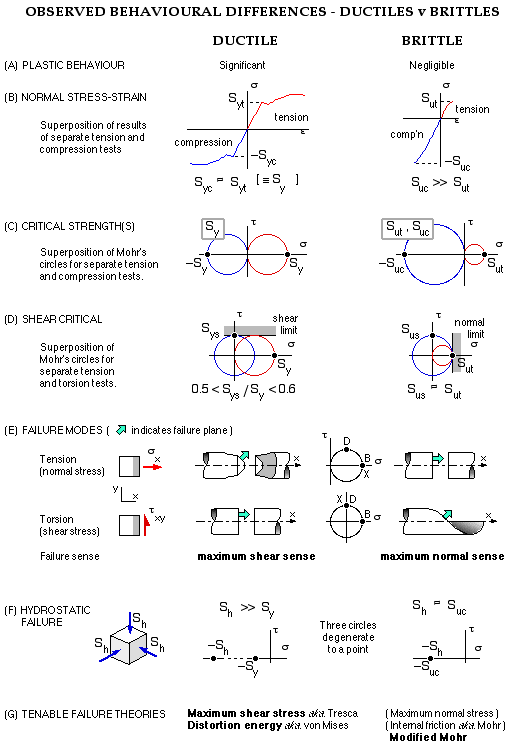
Currently no universal attribute has been identified which enables prediction of failure of both ductiles and brittles to an acceptable degree of accuracy. To appreciate why this is so, it is useful to recall the differences in behaviour of ductiles and brittles, as outlined in the sketch below.
- Under normal stress, ductiles' compressive characteristics are approximately the same as their tensile characteristics (B,C below) whereas brittles are significantly weaker in tension - eg. Suc /Sut = 3.5 to 4 for the cast irons ( Suc and Sut are the compressive & tensile ultimates).
- A ductile's shear strength is about half its tensile strength whereas shear and tensile strengths are about the same in the case of a brittle. Superposition of Mohr's circles of sizes corresponding to these proportions (D) suggests that a shear-based attribute is relevant to ductiles, whereas a normal-based attribute to brittles. (Note: the two superimposed circles correspond to completely different stress states - they have been superimposed only to highlight the circles' relative sizes.)
This conclusion is reinforced when we consider the directions of the fracture surfaces under normal and shear loadings (E). Thus in tension, ductiles fail at 45o to the load sense, which is the direction of maximum shear. This same 45 o fracture sense is found with brittles under torsion, however in this case the Mohr's circle is centred on the origin thus indicating a maximum normal attribute for brittles.
- A final qualitative argument involves strength under hydrostatic pressure, for which the three Mohr's circles degenerate to a single point (F). Brittles fail when the pressure corresponds approximately to the compressive strength, but it is difficult to assess when ductiles fail as the hydrostatic strength is so large - the absence of failure may be equated to the absence of shear.
The upshot of these observations is the adoption of the failure theories indicated - using
- shear-based attributes for ductiles
- normal-based attributes for brittles
These theories are examined below.
We refer to the equivalent stress σe for a ductile material only, as the uniaxial stress which has the same failure tendency as a given triaxial state - on the basis of whichever attribute is relevant. The safety factor then follows from ( 1a) as n = S/σe.
Distortion Energy Theory ( aka. von Mises Theory )
It may be shown that the specific distortion (or shear strain) energy for a linear material under the triaxial state (σ1, σ2, σ3 ) is proportional to
[ ( σ1 - σ2 )2 + ( σ2 - σ3 )2 + ( σ3 - σ1 )2 ].
For a uniaxial stress ( σe, 0, 0 ), or merely σe, this expression becomes 2σe2. So σe is equivalent to the triaxial system - ie. gives rise to the same distortion energy - if :-
( 8) 2σe2 = ( σ1 - σ2 )2 + ( σ2 - σ3 )2 + ( σ3 - σ1 )2
The equivalent stress is often referred to as the von Mises stress, after the propounder.
Maximum Shear Stress Theory ( aka. Tresca Theory )
This theory postulates that if a uniaxial stress σe, and a triaxial stress state give rise to the same maximum shear stress, then the failure tendencies of the two states are identical; that is, σe is equivalent to the triaxial state. So, for the same diameter of the largest Mohr's circle :-

( 9) σe = σmax - σmin
; where
σmax = max (σ1, σ2, σ3 )
σmin = min (σ1, σ2, σ3 )
The intermediate principal - which happens to be σ2 in the sketch - has no effect upon failure tendency according to this theory.
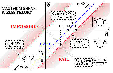
The failure theory appears as a series of lines at 45o when the minimum principal is plotted against the maximum principal, as shown below. Each point on this graph corresponds to a unique "largest" Mohr's circle and hence to an infinite number of stress states when the intermediate principal is considered.
 The 45o lines are each associated with a particular value of stress difference, ie. of equivalent stress from ( 9), and hence of safety factor. No point can appear to the left of the equality line on this graph, as this would imply a reversal of the minimum / maximum roles. The equivalent stress varies from zero on the equality line, through to the strength, S, on the failure locus (n=1).
The safety factor may be interpreted graphically as the ratio of intercepts on the axis of maximum principal, n = S/σe. The safe band extends to infinity in both directions as foreshadowed by the hydrostatic results.
Pure shear is represented by the line through the origin, perpendicular to the equality line, cutting the failure locus at a shear strength Ss which is half the tensile strength. This tallies with experimental findings as noted above.

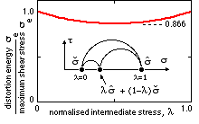
Either of the foregoing theories may be applied to ductiles: distortion energy represents experimental results somewhat better than does maximum shear stress. The small numerical difference between the two theories may be appreciated by defining the intermediate principal's value in relation to σmax, σmin by the parameter λ ( 0 ≤ λ ≤ 1 ) as shown in the sketch, substituting into ( 8) and invoking ( 9) to give :
σe DE / σe MSS = √ ( 1 - λ + λ2 ) ≤ 1 which is plotted here.
There is no numerical difference between the equivalent stresses predicted by the theories when the intermediate coincides with either extreme; the maximum difference is 13.4% when the intermediate lies midway between the extremes. The maximum shear stress theory is always conservative.
Both theories have their drawbacks in use - the distortion energy theory introduces non- linearities into otherwise linear problems, whereas the maximum shear stress theory requires the ordering of the principals - which is easy enough when these are enumerated but most awkward when the principals are expressed algebraically, as ordering leads to multiple possible expressions for the equivalent stress. The particularisation of the equations to plane stress is left to the reader ( see tutorial problem #16 ).
Modified Mohr Theory
This theory derives from the maximum normal stress criterion which historically was the first failure theory proposed for brittles, and is similar to the maximum shear stress theory in that the intermediate principal plays no part in the failure process. The concept of equivalent stress is not applicable to brittles owing to their differing tensile and compressive characteristics (250 MPa tensile has a much greater failure tendency than 250 MPa compressive) so the safety factor must be obtained from the principals and strengths directly, either graphically or numerically.
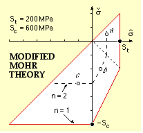
The maximum normal stress criterion failure locus is shown in σmax / σmin space at (a) below. The locus is defined by the two lines σmax = St the tensile ultimate, and σmin = - Sc the compressive ultimate; the two lines meet in the corner x. The pure shear line cuts the failure locus at the shear ultimate Ss - so this theory has Ss = St which we have seen is typical for brittles.
Above the line from origin through corner x, failure is dictated by tensile considerations; to the left of this line the compressive mechanism is more critical - so, to cater for both tension and compression :-
( i) 1/n = maximum ( σmax/St, - σmin/Sc )
Experimental failure points are shown; the theory is evidently dangerous to use for design in the fourth quadrant since points which the theory gives as safe lie outside experimental failure results.
Mohr's internal friction theory (b) overcompensates as it is unduly conservative in the fourth quadrant and unrealistic in prediciting a shear strength substantially less than the tensile, however the modified Mohr theory represented by the three linear segments of (c) describes experiments well. The third segment is defined empirically to pass through the points ( St, - St ) and ( 0, - Sc ), thus ensuring equal tensile and shear strengths; the addition of this third segment to ( i) leads to :-
( 10) 1/n = maximum (
σmax/St ,
- σmin/Sc ,
σmax/St -
( σmax+ σmin)/Sc )
The modified Mohr theory will be used in this course for brittle materials.
EXAMPLE
A component is made from a brittle material of tensile and compressive strengths 200 and 600 MPa respectively.
The table illustrates how the safety factor is evaluated at each of three different points (a), (b) and (c) on the component, the stress state at each point being defined by the three given principals which are tabulated.
| | principals, MPa | σmax | σmin | 1/n from ( 10)
| | a. | ( 100, 75, 50) | 100 | 50 | max( 1/2, -1/12, 1/4) = 1/2
| | b. | ( -200, 10, 50) | 50 | -200 | max( 1/4, 1/3, 1/2) = 1/2
| | c. | ( -200, -300, -100) | -100 | -300 | max( -1/2, 1/2, 1/6) = 1/2
| | The selected points all happen to lie on the n = 2 locus as illustrated.
|
| 
|
This script calculates safety factors for static stress states in ductile or brittle materials.
It should be emphasised that all the theories examined here relate to the fundamental static failure mechanism. Other common mechanisms, including fatigue and fracture of ductile materials in a brittle fashion, will be examined later in the course.
We have examined the individual steps in assessing safety of a chosen element -
- resolving indeterminacies if necessary to discover loads on the component of which the element is a part,
- application of load building blocks to establish stresses on the element,
- resolution of stresses to determine principal stresses, and
- application of a failure theory which is relevant to the element's material.
It's now time to string these steps together.
 Copyright 1999-2005 Douglas Wright
last updated May 2005


 The 45o lines are each associated with a particular value of stress difference, ie. of equivalent stress from ( 9), and hence of safety factor. No point can appear to the left of the equality line on this graph, as this would imply a reversal of the minimum / maximum roles. The equivalent stress varies from zero on the equality line, through to the strength, S, on the failure locus (n=1).


