Appendix - Indeterminate assemblies with multiple components
The model consists of two members A and B which
 are joined by a number of discrete identical connectors C - the assembly being subjected to an external tensile load F0. The distance between A and B is so small that rotational equilibrium is satisfied to all intents and purposes.
A and B are assumed to be in tension everywhere. Between the connectors, each segment of A and of B has an unloaded length L, and a compliance (reciprocal stiffness) of cA and cB respectively.

The precise manner in which the identical connectors deform is irrelevant, however their common compliance cC is known, and so the deflection of a connector is given by dC = cCF, where F is the force external to the connector exerted by A and by B.
We want to find out how the load transfer between A and B is shared between the various connectors - A could represent a bolt, B a nut and C a thread. The example illustrated will be examined - there are N = 5 inter-connector segments of A and of B, and N+1 = 6 connectors. Results for other numbers of connectors may be deduced by inspection.

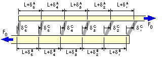
Compatibility The assemblage is shown deformed as a result of the external tensile load F0.
The extensions of succesive segments of A between the connectors are
δA1,
δA2 . . . etc, and of B
δB1,
δB2. . . etc.
The deflections of successive connectors are δC1,
δC2. . . and so on as shown. From the diagram, compatibility requires :
( i)
δCn+1 +
δAn =
δCn +
δBn
; 1 ≤ n ≤ N = 5

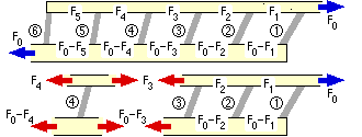
Equilibrium Let the forces in the inter-connector segments of A be F1, F2 . . . etc, while for equilibrium (of the RHS free body eg.) the corresponding forces in B must be F0 - F1, F0 - F2 . . . and so on, as sketched.
A free body of the typical n'th connector illustrates that the A/B force which is transferred through the connector is Fn-1 - Fn.
Constitutive laws For A and B in tension :
( ii)
δAn = cA Fn and δBn = cB ( F0 - Fn ) ; 1 ≤ n ≤ N = 5
and for the connectors :
( iii)
δCn = cC ( Fn-1 - Fn ) ; 1 ≤ n ≤ N+1 = 6 ; F6 = 0
Solution Inserting the 3N+1 constitutive laws into the N compatibility equations leads to the final N equations from which the N unknown forces may be found :
The equations for N other than 5 may evidently be written down immediately.
The fraction of the total load which passes through each of the N+1 =6 connectors, as found from solution of ( iv), is shown in the distributions below for B rigid and for various ratios cA/cC.
In the leftmost illustration both A and B are rigid therefore all connectors experience the same deformation - a fact that can be seen qualitatively by imagining A and B to be made of steel and the connectors to take the form of rubber blocks. Since all connectors deform in an identical manner they must transmit the same force, 1/6 or 16.7% of the external load on the assemblage, F0.
The compliance (flexibility) of A increases in the three other distributions illustrated above. The area under the distributions remains the same (F0), but it is apparent that the connectors at the right hand end of the assembly (where the unconnected A meets the connection assemblage) progressively take more of the load, until, as cA/cC tends to infinity, the first connector at the right hand end takes all 100% of the external load. This is the case argued qualitatively earlier when a flexible rubber bolt in a steel nut with steel connecting threads, stretches such that all the load is taken by the first engaged thread adjacent to the pulled bolt head.
Some further results from ( iv), in which B becomes progressively more flexible with respect to A, are also presented.
As may be seen, the effect of B's increasing flexibility is to place more load on the connectors at the left hand end of the connection assembly adjacent to the unconnected B, until, when the compliances of A and B are equal as in the rightmost graph, the load distribution is symmetric. If B's compliance were to further increase with respect to that of A, then the distribution would become skewed with the larger peak at the left hand end.
Although this simple model is somewhat unrealistic - for example in its assuming A and B are in tension only - the resulting load distributions are certainly realistic and confirm the general conclusion that the load distribution between components of a statically indeterminate assembly depends markedly upon the relative stiffnesses of the components.
A similar situation arises when the connector is continuous as in the case of a continuous weld C between A and B. The non-uniform load transfer is often referred to as shear lagand will be examined in the chapter on Welded Joints.
 Copyright 1999-2005 Douglas Wright
last updated May 2005

 are joined by a number of discrete identical connectors C - the assembly being subjected to an external tensile load F0. The distance between A and B is so small that rotational equilibrium is satisfied to all intents and purposes.


.gif)

